LEGO Building Techniques: Illustrated Troubleshooting
Most building techniques exist to solve one specific problem, so learn them backwards: start from the symptom, then apply the fix. A sagging floor needs cross bracing, not more bricks. Visible studs need SNOT, not more slopes. A corner that keeps separating needs one bridging 2x4, not a thicker wall. Below is the full mapping, with the measurements that decide when each technique is required rather than optional.
Two measurements underpin everything: the stud pitch is 8 mm, and a brick is 9.6 mm tall — exactly three plates at 3.2 mm each. Once you think in those units, most structural problems become predictable arithmetic instead of trial and error.
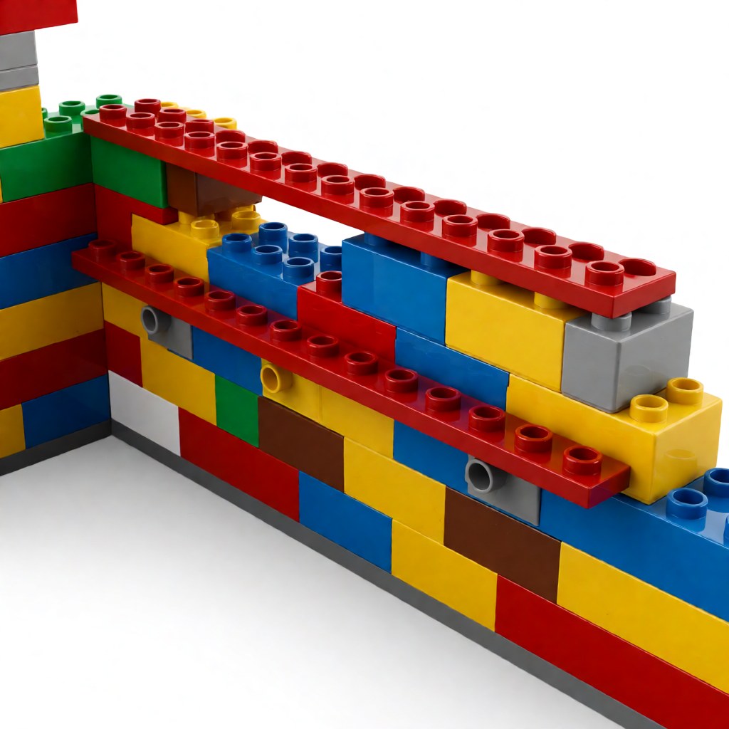
The problem-to-technique map
| Symptom | Underlying cause | Technique |
|---|---|---|
| Floor bows in the middle | Single-layer plate span with no bracing | Cross bracing with long plates underneath |
| Studs visible on a finished surface | Normal brick orientation | SNOT, then cap with tiles |
| Corner splits when handled | Joints stacked on one seam | Bridge the corner with a 2x4 or longer beam |
| Roof caves under its own weight | No internal frame; load carried at the perimeter | Multi-level interlock frame with load paths inward |
| Curves read as blocky | All geometry at 90 degrees | Stepped arcs, hinge bricks, or dedicated curved slopes |
| Front face looks flat | One brick type across the whole face | Layer slopes, tiles and textured plates for depth |
| Model leans after a week | Slow creep in an unsupported cantilever | Hidden support or Technic beam |
| Sub-assembly flexes when pressed | No cross-axis interlock | Long bricks spanning multiple joints every 3–4 courses |
Reinforce the foundation before you build upward
The bottom layer carries every layer above it, so brace it first. Three techniques, in order of cost:
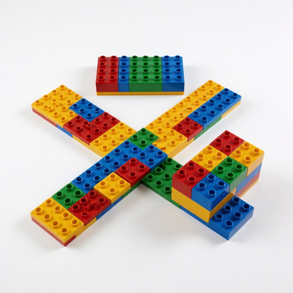
- Cross bracing. Two long plates under a baseplate, rotated 90 degrees to each other. A 16x16 base stiffened with two 2x16 plates stops bowing almost entirely — that is eight parts to fix a problem that otherwise shows up halfway up the model.
- Perimeter framing. A band of bricks around the edge of the base. Edge containment prevents a plate span from bowing upward at the centre, which is the failure mode that looks like a manufacturing defect but is really a design choice.
- Multi-baseplate joins. When you join two baseplates, bridge the seam with long plates spanning both and add reinforcement underneath. A butt joint with no bridge will open under handling.
When to brace, in numbers. If a span of unsupported plates is wider than about 16 studs (128 mm), brace it. Below that, a single plate layer holds fine. If the model above the floor will weigh more than roughly 500 grams, brace regardless of span.
Make surfaces read the way you designed them
Three techniques, in rising order of effort:
1. SNOT and tiles. Turn studs sideways and cap exposed tops with tiles. This removes the visual noise of stud rows and is the single largest jump in apparent quality per part spent. A surface that reads as "built" becomes a surface that reads as "modelled".
2. Slope layering. A stack of 1x2, 1x3 and 1x4 slopes gives a gradual transition instead of a staircase. Overlap each row by roughly half a stud to smooth the silhouette; use dedicated curved slopes when the profile has to be a true arc rather than a faceted one.
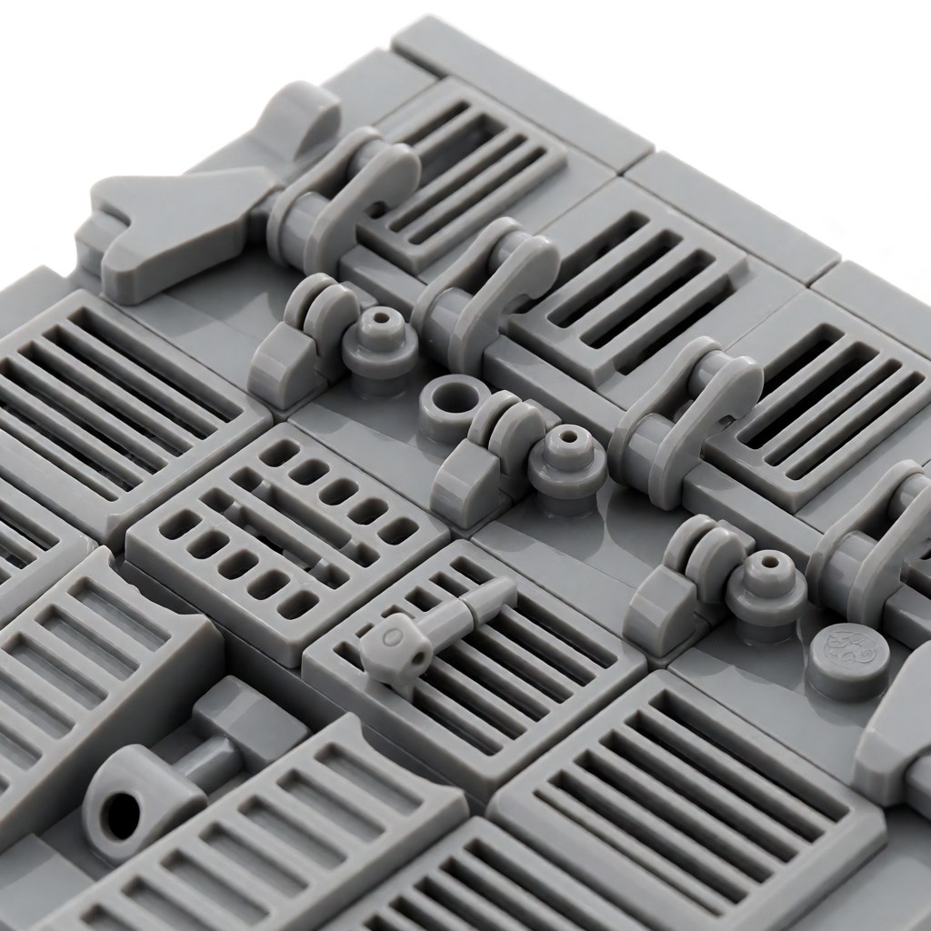
3. Greebling. Small mechanical detail — clips, grille plates, Technic pins, levers, textured tiles — applied in clusters. Three rules that separate greebles that read as designed from greebles that read as debris:
- Cluster, do not distribute. Evenly spaced detail looks like a factory pattern; clusters with gaps between them look intentional.
- Work in odd numbers. Groups of three and five read as composed; pairs look like an accident.
- Give it a focal point. One larger feature in a cluster, surrounded by small parts, reads better than uniform small parts alone.
Structures that survive being handled
Cantilevers and overhangs. Each course may extend outward by roughly a third to a half of a brick's depth. With 9.6 mm courses, that is about 3–5 mm per course, so a 30 mm overhang needs six to eight stepped courses — or a hidden support. Friction will hold a short overhang for years. A long one creeps: the tip dips a fraction of a millimetre per month, and after a year the model visibly sags. Use a hidden vertical support, a Technic beam, or a diagonal brace for anything beyond about 40 mm.
Arches and domes. Step small bricks one stud at a time for a soft curve, use hinge bricks for a faceted arch, then close the surface with slopes. Polygon approximation works better than most beginners expect: a hexagon formed from six 2x2 bricks reads as round at arm's length, and an octagon reads as round close up.
Spans and openings. When you cut a window or doorway, frame the opening on all four sides with a continuous ring of parts. An opening framed on three sides concentrates stress at the unframed corner, and that corner cracks first.
Load paths. Ask where the weight goes and give it an unbroken route from the heaviest element down to the base. A tower whose weight lands on one 1x2 column leans; spacing columns and bridging them with plates spreads the load and costs almost nothing.
Advanced technique: offsetting geometry exactly
Sooner or later you need a feature that does not align to the stud grid. Three tools, all exact rather than approximate:
| Tool | Offset achieved | Typical use |
|---|---|---|
| Jumper plate (87580) | Half a stud horizontally | Staggering a facade without changing the footprint |
| Headlight brick (4070) | One stud, recessed by one plate | Aligning features one plate inboard |
| 1x1 bracket (7919 / 36841) | One plate vertically | Attaching a smooth outer panel |
Because every value is a fixed multiple of 8 mm or 3.2 mm, a misalignment you cannot explain is nearly always a missing jumper plate rather than a design error.
Diagnosing faults you can already see
| What you observe | Likely cause | Fix |
|---|---|---|
| Slow sag at a cantilever tip | Creep under constant load | Add hidden support; do not simply add bricks |
| Hairline seam where two assemblies meet | No bridging plate across the seam | Swap to an offset bridging plate instead of pressing harder |
| Some joints tight, some loose | Mixed brands within one structural assembly | Rebuild the assembly from a single brand |
| Whitening at a clip or hinge | Stress from forcing a part past its tolerance | Reduce the interference; stop forcing |
| Plate span rising at the centre | No cross bracing | Brace underneath |
| Wall cracks along one line | Continuous seam from stacked joints | Stagger every layer |
Applying this to a MOC
Work in four phases and you will avoid most rebuilds:
- Block out the massing in cheap bricks — silhouette and proportions only, no detail. This is where you should be willing to throw work away.
- Prove the structure. Lift it, shake it gently, press the sub-assemblies. If anything flexes or clicks, fix it now, when the model is simple.
- Lock the technique set. One primary texture per face, plus one accent. Deciding this early prevents the patchwork look that comes from improvising detail face by face.
- Add detail last, and only where a viewer's eye will land — front faces, upper corners, anything at eye height.
The most common MOC failure is the opposite order: detailing a sub-assembly beautifully, then discovering the whole thing flexes and it all has to be opened up again.
Technique selection by model type
| Model type | Prioritise | Deprioritise |
|---|---|---|
| Architecture | Interlocking, corner joints, SNOT facades | Long cantilevers |
| Vehicles | Symmetry, cantilevers, curved panel work | Deep interior framing |
| Mecha | Ball joints, load spreading, hinged panels | Large unsupported spans |
| Scenes / dioramas | Flat foundations, multi-baseplate joins, terrain stepping | Weight-bearing columns |
| Large display pieces | Internal frame, modular sub-assemblies, hidden supports | Decorative detail in unreachable areas |
Four drills worth an evening each
- Foundation drill. Build a 16x16 flat layer three ways — unbraced, cross-braced, and perimeter-framed. Flex each by hand. The difference is unmistakable and takes about 20 minutes to learn.
- Wall drill. Build two 12-course walls, one with staggered joints and one with stacked joints. Tap both.
- Corner drill. Build a corner two ways: two 1x2 bricks, then one bridging 2x4. Lift both and compare how they open.
- Surface drill. Take one small facade and finish it twice: plain bricks, then SNOT with tiles. Photograph both and compare. This is the drill that changes how you design.
Both interlocking and overhang show up in nature builds, where a cantilevered platform has to hang off a tapered trunk without a straight wall to bite into. The treehouse MOC trunk and canopy guide is a good place to test them together on a 600 to 800 piece model.
FAQ
Q: What is the single highest-impact building technique to learn first? A: Interlocking with staggered joints. It affects every model you will ever build, needs no special parts, and fixes most stability complaints immediately.
Q: How do I know when a technique is overkill? A: When it adds parts without changing what a viewer sees. Detail facing a wall, or a frame under a floor nobody lifts, are both worth cutting.
Q: Can I apply SNOT mid-build, after the model is assembled? A: Usually not on a load-bearing face — removing stud rows changes the structure. Plan the surface treatment before you lock the layer, or keep the SNOT section as a removable panel.
Q: Do these techniques work with non-LEGO brands? A: Yes — they depend on stud geometry, which compatible brands share. The one caveat is clutch variance: keep a structural sub-assembly to a single brand so the joints behave consistently.
Read the techniques, then spend an evening using them on a small plan. The BrickPlan blueprint library has builds sorted by difficulty, so you can pick one that forces interlocking, SNOT and an overhang into the same model.